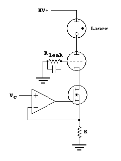
Current Regulator
All things being equal, electrical discharges may be started with a relatively high voltage and maintained with a lower voltage. This high-to-low voltage requirement is sometimes confusingly called a “negative resistance” characteristic. That is, once the discharge is struck, the effective resistance of the plasma decreases to an operating point.
Current can be controlled via a ballast resistor upstream from the laser anode; however, because of the voltage drop across the resistor, higher power systems will waste a lot of power in this resistor.
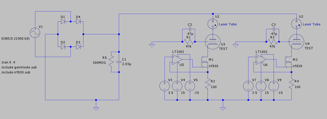
An alternative is an active current regulator that can handle the 20kVDC starting voltage and continuously regulate the discharge current. The regulator presented here is derived from that of John Doran, with some modernization and customization to suit my particular delusions of grandeur. The central current regulation circuit was outlined by Michael J. Posakony in “A High-Voltage Current Regulator for Laser Gas Discharge Tubes”, The Review of Scientific Instruments, Vol. 43, Num. 2, 1971. The basic design follows:
|
I will use the same triode that Doran used -- the 3-500Z. This triode is interesting in its own right, but I won't go into that here. Sleek and sexy since 1968, the 3-500ZG can be seen below. See Note 3 at bottom for some tube details. Anyway, the current is passed to the MOSFET and is regulated by the voltage Vc. The op-amp tries its best to make sure Vc appears at the MOSFET’s source. Overall, the current, I, equals Vc/R. I will need two of these circuits, sharing the +HV terminal, in order to control a dual discharge laser head. With the help of Proud Mary at 4hv.org, I've made a change to Doran's overall topology. Reflecting Posakony's design, Doran included 15V of positive grid bias to his design. Although Posakony's design includes the 15V bias, he also shunts that 15V through two BJTs to the triode cathode. In this way, Posakony's design has no potential difference between grid and cathode, thus preventing current flow. As I discovered in testing Doran's design, before the laser is lit, current will flow, violating the no grid current stipulation. |
|
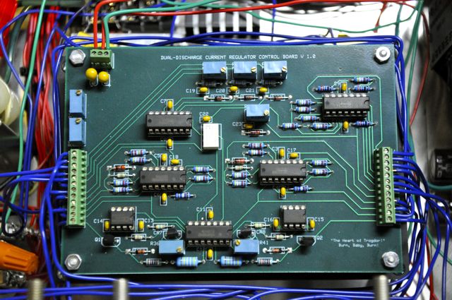
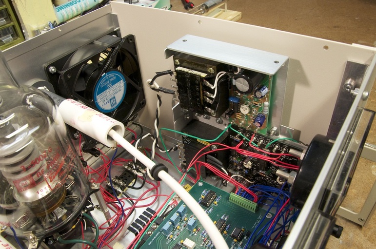
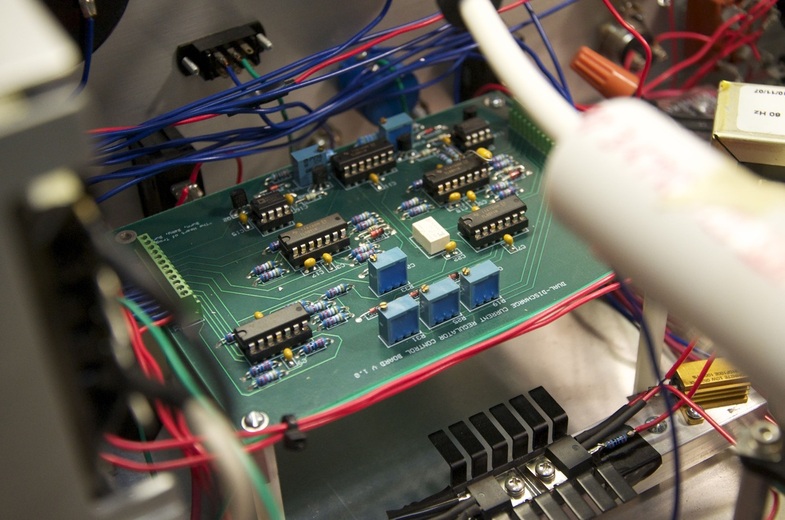
Doran built his instrumentation and control board from spare parts he had available. Some parts were obsolete or redundant. My updated design uses a laser-trimmed analog multiplier (AD633AN) and a 2.5V voltage reference (LT1009) in the overload control circuitry on page 4. Also I found a nifty 12V telecom relay (G6K-2P) that works great to switch between the two regulation channels’ characteristics displayed on the panel meters. I also cut out the tube filament warm-up circuitry because, as Doran explained, it is unnecessary with the 3-500Z triode.
In my design, R is a 100Ω, 10W chassis mount resistor. Since current is meant to vary between 0 and 80mA (per channel), Vc should vary between 0 and 8V. There are two channels that work similarly. |

|
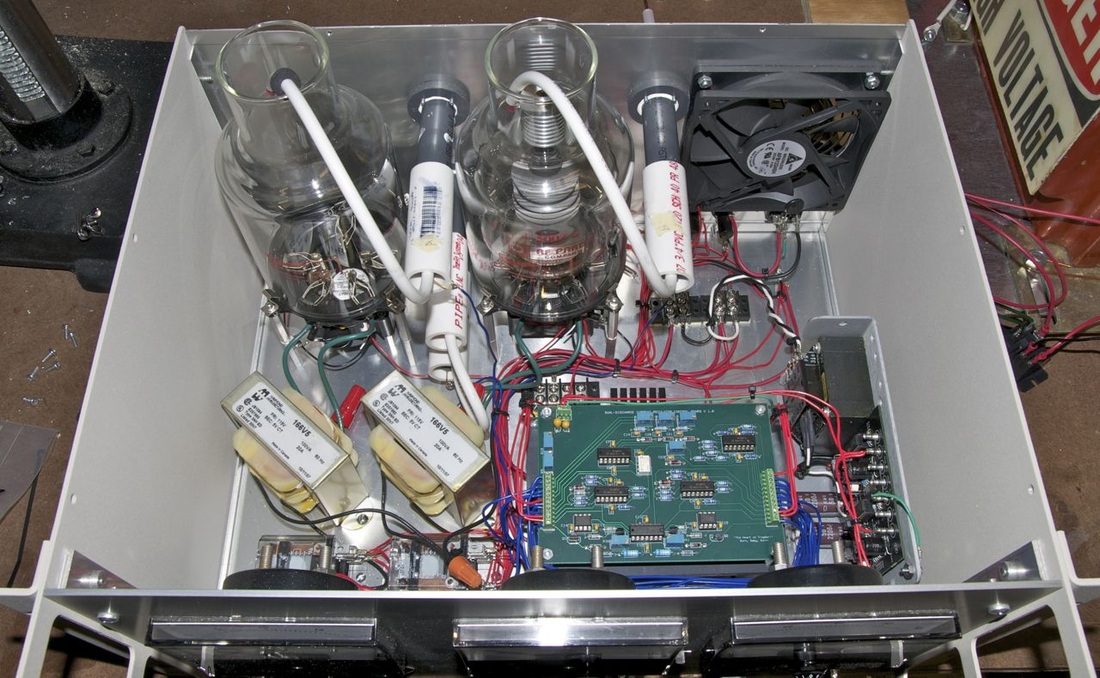
On 03/14/2011, a brand new RF Parts 3-500ZG triode arrived, having been donated by one of my rabid fans (my mom). This will allow the full testing of both circuits as soon as the HV supply is completed. The high voltage connectors have been replaced and installed.
I've recently (Feb2012) made changes to the wiring. A solid chassis ground was made, making it possible to remove several lengths of ground wires to a central terminal strip and make chassis ground returns. Also, the power supply terminal strip was removed from the side (it kept falling off anyway).
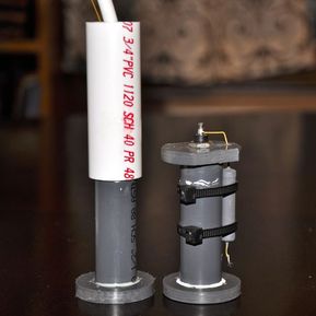
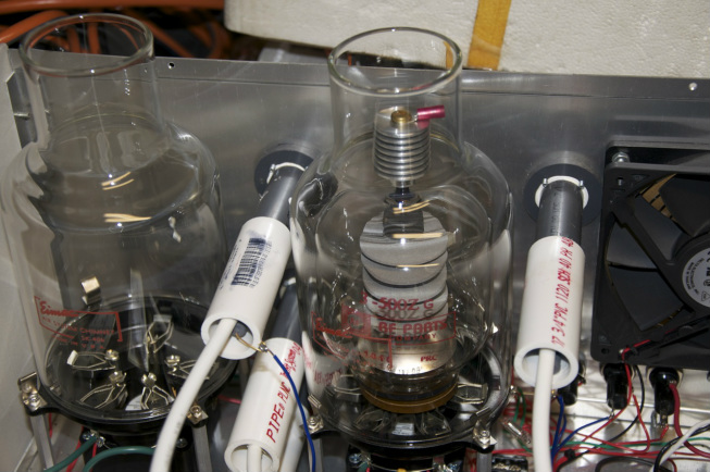
The grey pipe is 1/2” Schedule 80 PVC. It’s outer diameter is only a couple hundredths of an inch bigger that the inner diameter of the white 3/4” Schedule 40 PVC pipe insulator. With a little Dremel work on inside of the larger pipe, everything fit together nicely. All is held together with Gorilla PVC Cement. I partially filled the white pipe with Dow Corning 734 RTV silicone for insulation and mechanical strength.
For clarity, there is a 1/4” PVC sheet with 4-40 standoffs holding the control board up, but it also has a 24V switching PSU literally hanging underneath. The 24V PSU runs all the fans and auxiliary relays.

|
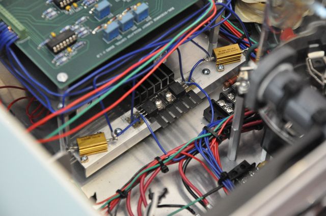
On the left is the new regulation section. I individually soldered lead wires to each FET leg. I reused the resistors, heat sink, and mounting hardware. The shrink tubing was used to insulate the drain and source, while the gate resistor was soldered directly to the gate pin. Otherwise, this is just a replacement for the damaged part. A little electrical tape went a long way to insulate the gate resistor from the aluminum heat sink. |
|
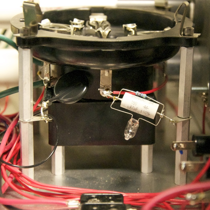
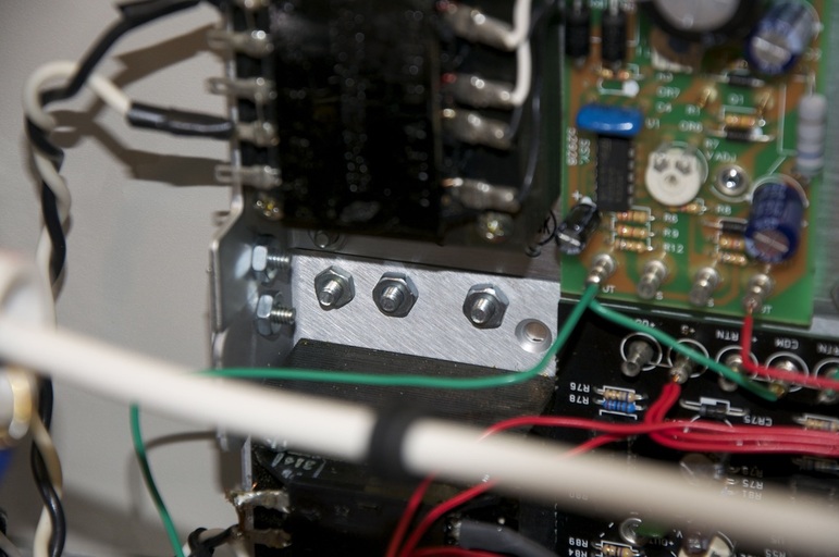
On the right you can clearly make out all of the revisions made to the triode tower. The grid is grounded via a 47kΩ resistor and .47μF capacitor. The neon lamp provides a measure of over-voltage protection. In simulations, the capacitor seems to do a smashing job of controlling the initial strike voltage surge at the cathode. See the simulation results below. Also, you can see a TVS diode and metal oxide varistor (MOV) tying the cathode to chassis ground. They are set to clamp very quickly at ~270V. In retrospect, I should have set the TVS diode to clamp around 150V and dialed down the MOV a bit, but there it is. |
|
Thus, the “cooling towers” were born.
It took a bit of reviewing fans’ static pressure charts to figure out how big a case fan was needed. I picked one that could move enough air to keep both tubes cool, even if the boost fans were not there. Then, I added a fan control knob to the front, in case it proved overpowering. When only one tube is running, that tube’s boost fan capitalizes on most of the case pressure.
You'll notice that the SK-406 chimneys have been expertly modified (read: not by me) with extensions that will pass through the case top and insulate the surrounding components from the high voltage inputs.
The sufficiency of this cooling arrangement is still a high-risk unproven application. I'll update when I've left it running for awhile without it... you know... exploding.
On 11 Jan 2012, I made the holes in the case top for the tube chimneys and connecting wires. To smooth the edges of the holes surrounding the chimneys, I bought 2 feet of 40kV wire that I slit, removing the wire, and press fit over the edge. I think this greatly increases the fan efficiency and keeps the aluminum edges from scraping those expensive chimneys.
I’m working on some water-slide decals for the instrument panel. See Note 4 below for decal mishaps in laser printers.
Simulation
Setup, Calibration, and Experiment
(1) Operation with 600VDC from power supply tied directly to vacuum tube anode. I picked 600V because 500V sounded wussy and 1000V sounded too dangerous to my Fluke DMM. I began with the current control at its minimum position, reading 0mA, with the milliammeter in series. As I increased the current through the circuit, the input voltage dropped. At first this observation confused me until I realized that the filter wasn't keeping up with the current demanded between cycles. My second observation was that the current would not increase beyond a certain point. I believe that the triode just wouldn't conduct the demanded current and such low plate voltages.
(2) I re-calibrated the current meter and input voltage meter, discovering that I must have done it pretty good the first time. I had used batteries as low voltage, post-divider, voltage sources and pseudo-current sources then.
(3) Lastly, I connected the power supply to the input voltage meter and ran it up to 20,000V. This is the voltage where electrons start jumping all over the place, and sure enough, I heard a buzz coming off of a bare wire that was a couple inches from ground. No problem, right? Just turn off the power supply and let the capacitor bleed. Only to turn off this power supply, I had to physically unplug it from a power strip. Remember the return path for the power supply is earth ground. I essentially created a multi-kV floating potential from the huge steel plate that everything is mounted on. The meters on the regulator went all cockeyed too as their inputs were now floating with respect to their case, still earthed. To add insult to injury, I thought it would be a great idea to plug the power supply back in. The gentle zip-zap as I approached the socket let me know that the ground pin was not going to let me get away with this one. Nothing appears to be damaged, and we'll get back with this later. I am happy that when mounted, that return path will be guarded against some level of stupidity.
On 19-20 January 2012, I tested my regulator with a 2mW HeNe laser. I discovered the following:
(1) By manually turning my Variac up to the starting voltage (~10kV) with the FET clamped, I can over-volt my FET with a sustained burst of HV in an instant.
(2) Over-volting a FET damages my regulation op-amp chain, causing it to short its supply power. The FET's leads were too closely soldered, anyway.
(3) Throwing the random resistor on the laser anode will cause loud flashover crack that will finish off that already accidentally shorted power supply.
(4) Unsurprisingly, with the positive grid bias of the old design, current will flow in the grid (bad).
The following steps were or are being taken:
(1) There will be robust over-voltage protection placed on the FET drain. This seems essential for the laser start condition, especially.
(2) The grid will be grounded with a grid leak resistor and complementary capacitor in parallel for RC time constant, in addition to over-voltage protection in the form of a NE-2 neon lamp.
(3) Relays have been installed in the power supply to allow the HV to be switched as well as a momentary start relay, rather than manual adjustment.
|
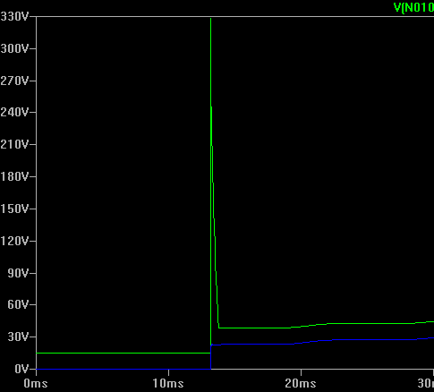
This simulation shows the difference between the voltage across the FET in my old positively biased design (green) and my new grounded grid design (blue). Both of these are at 1/100 mA -- as I approach a completely clamped FET. As the allowed current approaches zero, the cathode spikes too quickly (dV/dT), and often too much (>500V), for the FET during discharge ignition. A .47μF capacitor and 47kΩ resistor ties the grid to chassis ground in the new design. The capacitor seems to be the essential element in damping the spike on the cathode.
|
Back after the long break... (April 2014)
Once the laser started, the fans indeed stopped again along with the whining I observed earlier. But as I decreased the input voltage and left the current around 8-10mA, the fans suddenly popped back on and the laser discharge looked steady.
This leads me to my current theory: I think that at certain current/voltage settings an oscillation starts up, probably between the laser tube and power supply or vacuum tube. These oscillations make their way into the 24V switching supplies and its supply to those DC fan controllers. The power supply and/or DC fan controllers then freak out.
I'm in the process of replacing the switching 24V supply with a linear supply and replacing the 24VDC main case fan with a 120VAC fan that will always be on when the power is switched on. I'm pretty sure that we will maintain at least case pressure. The worst that can happen is that that tube boost fans will be glitchy when in that weird mode. Otherwise the regulator operated as it should.
I took a small piece of aluminum flashing, nibbled out a rectangular piece, doubled it over and pounded it flat, then wrapped it around the two PSUs chassis holes. I drilled the appropriately-located holes, then I passed some bolts through it to hold it together, Frankenstein-fashion. In fact my passion for bolts is pretty crazy on this project. Everything is reversible because it is held together with bolts.
Everywhere.
The board is mounted on 4-40 aluminum standoffs and the simplest way I could think to mount them to 6-32 anything was to just screw the 4-40s into the 6-32s, thus somewhat stripping the nylon standoffs.
This actually turned out to not be a bad compromise. The nylon is pretty robust as long as you don't torque it too much.
Notes:
- The TL084s above (the 14-pin ICs) are really four operational amplifiers (aka, op-amps) in the same package. Op-amps became my favorite components in the current regulator when I learned how many cool things they can do. If you look closely at my circuit, you’ll discover that they are being used to add, subtract, act as a Schmitt trigger, buffer inputs, and act as inverting amplifiers. And they can do so much more.
- I was always surprised by the high quality of components supplied by Digikey and the other big name electronics distributers. The prices were a bit more than I would like, but several times I would have to replace a part I bought from a hobbyist or discount distributer because it just didn’t work. For example, a panel mount DPST switch that I bought from AllElectronics had a M12-0.75 pitch thread. This proved impossible to find a dress nut for. So, I bought a new switch and dress nut from Digikey -- perfect.
- With the help of Steve McConner at 4hv.org, I was finally able to make sense of the 3-500Z datasheet and see why Doran selected this tube. To understand the suitability of the components in the regulator circuit, McConner suggested considering two cases: with the FET fully conducting and when it was nearly non-conducting. What follows is what I understood: (Case 1) Assuming a plate to grid voltage (Vp-g) of 5000V and a filament to grid voltage (Vf-g) of -15V (The grid is positively biased and the FET fully conducting, so the filament voltage is 0V), the tube should conduct hundreds of milliamps. Even when Vp-g equals ~ 0, the tube should conduct ~100 milliamps. So, it will definitely be able to pass 80mA, if asked by the FET. (Case 2) Now, we’re going to try to make the plate as tantalizing as possible to the electrons, but deny them to flow freely by clamping the FET. If Vp-g equals 20000V and 15V is on the grid, this puts us way off the chart. We can approximate the near-linear 1ma line with Vf-g = .006452 x Vp-g + 2.5V. In this case, if we were to put 20000V on the plate and allow 1ma through the FET, there would be ~130V on the FET drain. Of course we have to add the 15V on the grid, for a total of ~145V on the FET drain. The IRF830 laughs at this, with its 500V max voltage rating. This is assuming a 1mA current, which is by no means negligible. But I think we can assume that if it were to drop to near-zero, we should still be within voltage tolerances. When I receive the tubes, I’ll test the actual no-load cathode voltage.
- Water slide decal paper completely destroyed the fuser sleeve in my HP LaserJet 1320. The fuser was cool and everything -- poof. The self-repair is ~$50 and in my case, unsuccessful. I think I broke one of many little plastic legs that apparently, if broken, causes a horrible, loud grinding noise. The apparent alternatives were to buy a $100 HP fuser assembly or a $100 refurbished LJ 1320 -- went with the latter.
- On 22Dec11, I discovered that LTSpiceIV runs flawlessly in Wine on Mac OS X Lion. Wunderbar! Now the family can check their email and what-not without me having to restart the computer from Windows XP to OS X.
